Sunday, 6 October 2013

First Engine Start

6th October 2013

The control cables are now routed correctly down to the back end.


As there's not much work about just now, I've been able to get on fairly quick with the rebuild. I would have been even further along if our hot water tank hadn't given up the ghost and needed replacing! That set me back a couple of days.


This shows me doing up the rear end connections of the control cables, clutch, gears and what have you. All quite fiddly and quite difficult to eliminate any backlash from the cables.


I remember from when I was 16yrs old, (that's some memory), having lots of problems with the little trunions and 3mm Allen grub screws that clamp the cables into their operating links.


The brass bit in the middle is the trunion. Having bought new ones, I find they come with a tiny steel disc about 3mm diameter that sits on top of the cable. This prevents the grub screw cutting or damaging it. Never heard of those in the 60's, no wonder we had so much trouble keeping cables tight.


Now where does this bit go? Oh hang on, it's the knackered hot water tank!!


Ok that's them all done up. I've since noticed one of the gear cable outers had slipped out of its housing in the headstock. No wonder I can't select 1st gear. Not to worry, I'll adjust it later, I'm too close to starting the engine to stop now.
 

Round t'other side that's the carb fitted and connected. I stripped the carb and cleaned the jets as it has been sat on the shelf for about 6 months. The new fast flow fuel tap seems OK and I've added an inline fuel filter just for good measure. With the new fuel tank, tap and filter I should get away with having to clear the fuel jets every five minutes as before.


That's the choke lever on the left, up for off down for on. The right hand one is the fuel tap, up for off, horizontal for on, fully down for reserve fuel.


Here's a not very interesting photo showing the choke cable (the top one) with it's stainless steel guide for keeping other cables away from the hot cylinder cowling.
 
Note the original aluminium cable tie round the frame. I thought I'd use these instead of modern plastic ones for a bit of authenticity. I bought 6 in accordance with the Scooter Restorations parts catalogue but find I need about 12.  OK so I now have a mix of the old and new.
 

Back on the deck. I wonder what I'll do with the mobile work stand when the scooter is finished?


After all the work and expense fitting the new kickstart shaft (and other K/S bits) it seems sensible to fit the kickstart lever. I have to say, it fits snugly onto the new splines.


I put a litre of juice in just to see if it will start. No sign of any leaks from the new fuel pipes or carb, it's getting close to engine start time now.


It took a while to get the fuel through but it sounds good with a nice even tick-over. I can't wait to get on the open road and let loose the whole 9.38 horse-power!!

Note: There should be a video of me starting the engine above here. It doesn't seen to play on Ipads or tablets but is OK on laptops and PC's for some reason.


Saturday, 28 September 2013

Engine Refit

Saturday 28th September 2013

Now the chain casing is back on, it's time to dress the engine ready to refit.


First, on go the brake shoes, brake drum and brake operating cam and arm.

Next, the clutch and gear linkages, also the gear cable adjuster block.


The barrel (at the exhaust port) has been welded adjacent to one of the studs in the past and it looks like it was machined down with a hammer and chisel. One of the studs was a bit loose but seems to have tightened up OK. The exhaust pipe plus new gasket seems to have tightened up OK as well. 
 
I can see a time in the future when I'll need a new barrel, maybe uprated to 200cc! That's my birthday and Christmas presents sorted for a few years. 
 
The flywheel and cylinder cowlings go on next. It's a lot easier to fully dress the engine while it's on the bench, then fit the whole unit.  


Who's that in my shed, oh it's me. Sheena's got hold of the camera again.


Engine and frame reunited at last!


Now it looks a bit like a scooter

Handlebars, Kickstart etc

Wednesday 25th September 2013

Still no sign of the spares for the kickstart, which would have allowed me to get the engine rebuilt and back in the frame.

Never mind, I need to press on as I'm missing this beautiful riding weather. Plenty to do at the handle bar end as this is where everything comes together on a Lambretta.


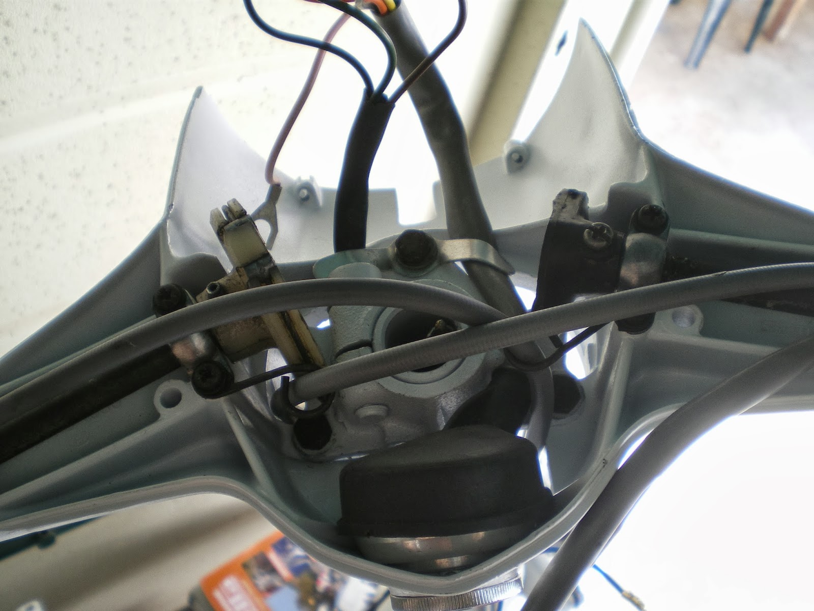
Here's an overhead view of the headstock


In here we have plenty of cables, i.e. one for the clutch, one for the throttle, one for the front brake, two for the gears, not to mention the speedo cable, ignition switch and three assorted wiring looms. I still have to find room for the bulb holder and headlamp. 

It's a tight squeeze normally but as my modified wiring system (chocolate blocks) has to fit in as well I might have to get Sheena to sit on the top cover while I do up the screws!!


As I still have nothing to connect all the cables to, I've stuffed them into the toolbox to keep them out of the way.

Might as well assemble and fit the front wheel and brake, that gets the speedo and front brake cables out of the way.


Three cheers, the parts have finally turned up, on with the new kickstart shaft and chain guide


That's the new modified (nylon) upper chain guide fitted and locked, simples.


This is the new kickstart return plate bolted in with three new bolts. To the right is the old one which is nothing like the new one, fingers crossed it works OK.


Oi! get off my camera Mrs A.


I think it goes about here!
 

Kickstart shaft in place with new spring (the old one was cracked). This shows the kickstart piston teeth retracted.

I'd never seen a kickstart mechanism before, it's quite a canny bit of engineering.


This with the teeth poking out ready to connect with the 1st gear and turn the engine over.
It seems to be working OK, lets hope it does when it's put together.


That's the before and after shot with the new shaft in place. There's nothing worse that a floppy kickstart, I'm too old for bump starting.

Now the chain casing is back on the engine along with a new gasket and the kickstart seems to be operating nicely.

.


Newly painted petrol cap, not sure why it's in this section but here it is anyway!


Saturday, 21 September 2013

Fuel Tank and Toolbox

Saturday 21 September 2013

No sign of the parcel of spare parts I was hoping for this week. I wanted to get the kickstart re-assembled and the chain guides sorted so I could put the engine back together and get it fitted.

Never mind, there's plenty of other bits to get on with such as the fuel tank.


This is a new stainless steel tank from Cambridge Lambretta. It looks like something off a McLaren F1 car. When the bike was running previously, the jets in the carb would block up regularly which was a nuisance as it was a carb strip each time to clear them. The old tank was quite grotty inside even though it had been treated with Petseal which was supposed to seal up the rust etc.


The fuel tap is a modified fast flow type with rear outlet (Cambridge Lambretta). The original fuel outlet was tight up against the engine mounting and flywheel cowl which made it awkward getting the fuel pipe on and off and could lead to a kinked pipe / fuel starvation.

The fast flow bit does what it says on the tin, it's especially good for high performance tuned engines. (Maybe one day??). When the fuel tank goes on to reserve, there is a time lag before you can make the switch on the fuel tap, so the engine, being a two stroke, runs without lubrication. The fast flow gets the fuel and oil mix there quicker, so I'm told. Time for another photo.


The filler cap looks a bit scruffy, I'll give it a coat of paint later.


Bottom half of the headstock in place


Rear brake pedal fitted ready for its cable


Toolbox and door in place


From the back


Lambretta in the '60's thoughtfully provide a tool box, handy for your two stroke oil, a few essential tools and for hiding recreational medicine - allegedly!


Tuesday, 17 September 2013

Starting at the Back

Tuesday 17 September 2013

I decided to start at the back end as there are a few fiddly bits and certain things have to be assembled in the correct order, as I discovered on the dry re-build.


The voltage reg. needed to be moved forward from its previous position as it was difficult to connect the wires, the mudguard being in the way. This meant drilling new holes in the frame and tapping out to M6. While I had the drill going, it seemed sensible to drill a hole for the assorted earth leads.


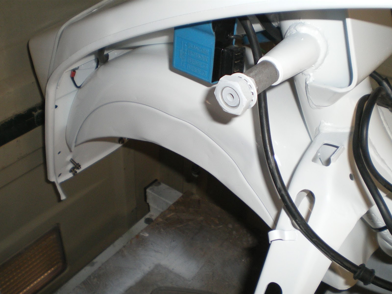
This blue thing is the CDI unit (capacitor discharge ignition) which sounds like a modern version of a coil, i.e. it produces the high voltage for the spark. I fitted it to the existing mounting holes but it just doesn't seem in the right place to me. The holes would have been for the old 6v coil.

Sure enough, it is fouling on the back mudguard.


More holes drilled in the frame, it's starting to look like a Swiss cheese now. This part of the frame is not really load bearing at this point so no probs. It's now clear of everything and looks much better.


It may seem an odd time to add chrome-work but the nuts and bolts for the rear carrier are a sod to get to with everything in place, so on goes the back rack along with the back light unit.


The photo below is me looking a bit confused, not for the first time!


Got it figured out now, time for a break.


Sunday, 15 September 2013

Final Build

15 September 2013

Here I am back in Cyprus and have finally made a bit of time to start the final build.

Whilst I was in UK I called in at Cambridge Lambretta, (along with my son Jamie), to get a new speedo. A very helpful guy called Ian sorted out an SX style speedo for me, and Jamie decided to buy it for my birthday. Very nice thanks Jamie.

This left me some spare cash so I decided I would go the extra mile and get a new kickstart shaft as the splines on mine are badly worn.


Not a great photo but take it from me the splines are badly worn. I'm certain if I don't fix this now it will come back to haunt me later.


The chaincase came off with very little effort.


The tangled lumps of metal used to be the upper chain guide. Luckily they didn't get caught in the gears which if they did, could have jammed the works well and proper.


Another poor photo I'm afraid but the damaged bolt is one of the chain guide retaining bolts.  The bit it's resting on is the knackered upper chain guide. Without the guide, the chain has been sagging and wearing the bolt away. As far as I can tell, the chain is OK, it obviously must be made of harder steel than the bolt.

I have since learned that the original chain guides were not up to the task and uprated nylon ones are now available.

On inspection, the kickstart piston is a bit worse for wear and the return spring has a crack in it. There is some burring to the return guide block also. Looks like all the kickstart components need to be replaced

All the new parts are now on order and hopefully will be here in a week or so.

There's plenty to be doing in the mean time so I fitted the voltage regulator and CDI unit today.

The regulator was originally attached to the rear footboard support strut but now is on the rearmost upper frame tube opposite the CDI unit where it should be. This meant drilling new holes in the frame and tapping them out to M6 and fitting new mounting bolts. All done now so the wiring harness can be fitted next.